EnvSeq
EnvSeq is a clocked envelope sequencer. Each step outputs a configurable shape (ramp/exp/log/flat/VOSC), with per-step level (Amp), offset, probability (chance to play), duration in clocks, optional retriggers (repeating the shape within the step) with fade, and per-step length (time-warp of the shape inside the step).
I/O
| 1/3 | 2/4 | |
|---|---|---|
| TRIG | Clock (timebase) | Reset (or step trigger when TR2 is enabled) |
| CV INs | Mod 1 (per Mod1 mode) | Mod 2 (per Mod2 mode) |
| OUTs | Envelope CV | Assignable (Out2 mode) |
UI Controls
EnvSeq has two screens:
- Main screen: Mod1 mode, Mod2 mode, Out2 mode, Randomizer, TR2 mode, number of steps, Reset, Init.
- Step screen: Step number, shape (VOSC waveform index included), and per-step parameters (offset, amp, VOSC options, probability, triggers, clocks, length, retrigger fade, Mod2 mark, Copy/Paste).
Mod1 (CV1) modes
Mod1 defines how CV1 is sampled/applied:
| Mode | Description |
|---|---|
| Mod | CV1 is applied continuously to every step’s CV output. |
| H step | Sample & hold CV1 at each step start. The held value is used for the whole step. |
| H seq | Sample & hold CV1 at the start of the sequence. The held value is used until the next sequence restart. |
Mod2 (CV2) modes
| Mode | Description |
|---|---|
| Length | CV2 modulates the Length parameter (time-warp of the shape within the step, bipolar, 1-200%) |
| StepSel | CV2 selects the next played step (unipolar 0–5V mapped across the active num_steps). The selection is sampled on the clock when advancing steps. Step Probability is ignored in this mode, but multi-clock steps (Clk) are still honored (the current step holds until its clocks are done). |
| RetrgLvl | CV2 modulates the Retrigger Level (-15..15). Negative values fade in (0%→100%), positive values fade out (100%→0%), 0 = no fade. |
| Mod | CV2 is added to the output CV for all steps. |
| ModMark | CV2 is added to the output CV only on steps marked with Mod2 in the step editor. |
| GateLen | CV2 scales Gate Length (1–200% of the per-step gate length) for gate-based outputs. |
Out2 modes
Output 2 can mirror or complement the main envelope output:
| Out2 Mode | Description |
|---|---|
| Cpy | Copy of Out1 (same envelope CV) |
| Inv | Mirrored copy of Out1 within the step’s amplitude range (vertical flip). |
| InvO | Mirrored copy of Out1 around the step’s waveform offset (0–100% of amp). |
| HStart | Holds the step’s start CV value until the next step begins |
| Step | Short gate at each new (played) step |
| StepTrg | Short gate at each new (played) step and retriggers within a step |
| Seq | Short gate at the start of the sequence (on wraparound) |
Notes:
- Gates are only generated for steps whose Shape is neither
HoldnorZero. - Gate pulse length is set per step via Gate Length and can be modulated by
GateLen.
Step screen
After the main page items, the cursor enters per-step editing. The viewed step (the one you edit) is independent from the currently playing step shown on the main page.
Step number
Select which step number you’re editing.
Shape
Shape for the step:
Hold: silent step (holds the previous step’s output CV and generates no gates)Zero: outputs 0V but still counts as an active step (no gates generated)Flat: constant level (Amp)ExpDw: exponential-like Amp → 0ExpUp: exponential-like 0 → AmpRampDw: Amp → 0RampUp: 0 → AmpLogDw: logarithmic-like Amp → 0LogUp: logarithmic-like 0 → AmpVOSC: vector-oscillator waveform driven by step progress (shows a waveform number)
Parameters
Offset
DC offset added to the step output (and used as the center point for InvO).
Amplitude (amp)
Bipolar amplitude of the step’s shape; negative values invert the shape.
Waveform offset (WaveOff)
Shifts the waveform relative to the step offset (0–100% of the step amp). Applies only when the Shape is set to VOSC.
Revert
Runs the waveform phase backwards. Applies only when the Shape is set to VOSC.
Invert
Flips the waveform vertically. Applies only when the Shape is set to VOSC.
Option
Post-process the waveform. Applies only when the Shape is set to VOSC.
None: no post-processing.FoldUp: reflect upward the values below waveform offset.FoldDw: reflect downward the values above waveform offset.ZeroUp: zero out values above waveform offset.ZeroDw: zero out values below waveform offset.
Triggers
Sets how many times (1-8) the shape triggers within the step.
Clocks
How many incoming clocks (1-8) this step lasts.
Length
Time-warp of the shape progression within the step (1–200%).
- <100%: shape reaches the end early and then holds its final value for the remainder of the step.
-
100%: shape progresses more slowly (may not reach the end before the step completes).
- If
Mod2mode isLength, CV2 scales this per-step value.
Probability (Prob)
Chance (0–100%) that this step will be played when the sequence reaches it.
Retrigger Level (RetrgLvl)
Sets the retrigger fade behavior in the range -15..15:
from 1..from 15: substract from first trigger and fade in from it to 100%no: no fade (all retriggers at 100%)to 1..to 15: substract from last trigger and fade out from 100% to it
Mod Mark
Marks this step as eligible for Mod2 when Mod2 mode is ModMark.
Gate Length (GateLen)
Sets the gate pulse length for gate-based outputs:
- ~0.05–1000ms with an exponential curve
- 1–100% of the step duration
- If
Mod2mode isGateLen, CV2 scales this length
Copy / Paste
Copy the current step’s settings and paste them onto another step, even across hemispheres. Paste is only shown when the clipboard has data.
Random
Selecting Random on the main page opens a scrollable, checklist-style randomizer for step parameters:
Offset: randomize step OffsetsAmp: randomize step AmplitudesShape: randomize step ShapesVOSC: allow randomizing VOSC waveform numbers when Shape isVOSCTriggers: randomize step Triggers (occasionally)Clocks: randomize step Clocks (occasionally)Length: randomize step LengthsProb: randomize step probabilities (50-100%)RetrgLvl: randomize step Retrigger LevelsModMark: randomize step Mod2 marksGateLen: randomize step Gate Lengths (1..50%)
Select Apply to apply randomization and return to the main view, or Back to exit without changes.
TR2
When enabled, TR2 (input 2) replaces TR1 as the step-advance trigger. TR1 still provides the clock timebase for step length. When disabled, TR1 advances steps and TR2 acts as Reset.
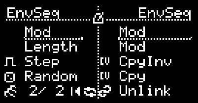
Linking (paired hemispheres)
When both hemispheres run EnvSeq, you can link them to add two extra modulation inputs and two extra outputs.
- Link is enabled from the right hemisphere. On the right EnvSeq main screen, select
Linkto enter the linked view. - The right hemisphere becomes a linked control panel: it no longer runs its own sequence.
- Mod3 / Mod4: the right hemisphere’s CV inputs become two additional modulation sources. Each has its own Mod mode (same list as Mod2).
- Out3 / Out4: the right hemisphere’s outputs become two additional Out modes (same list as Out2).
- The left hemisphere continues to run the sequence and computes the actual CV/gate values for Out3/Out4.
- Select Unlink on the right to return to normal operation.
Credits
Authored by Daniel Gorgan