Quantermain
Quantermain is a 4-channel quantiser which expand the one from Mutable Instruments Braids with interactive scale-edit functionalities. 48 editable preset scales are included, plus 4 fully user-definable scales (with additional finetune/microtonal edit options).
The output accuracy should be excellent (is fairly excellent) due to the use of a precision Texas Instruments 16-bit DAC; the input side uses the Teensy internal ADCs, with 12 bits of effective resolution, which should be more than enough for almost all purposes. The trigger-to-quantised-output latency is also very decent: < 100 microseconds.
Controls
| Left Encoder | Right Encoder | |
|---|---|---|
| TURN | Select channel, or note in scale in scale edit mode | Navigation mode: move up and down through the menu items. Edit mode: increase or decrease the value being edited. |
| PRESS | Increment channel by one | Toggle between menu navigation (selection) mode and value editing mode |
| LONG | App selection menu |
| Up Button | Down Button | |
|---|---|---|
| PRESS | Transpose up one octave for currently displayed channel | Transpose down one octave for current displayed channel |
| LONG PRESS |
I/O
| 1/2/3/4 | |
|---|---|
| TR | Mappable as the trigger input for each channel A to D, independently |
| CV | Mappable as the external CV input to be quantised for each channel A to D, independently |
| OUT | Output voltage for respective channel (quantised if quantisation is enabled) |
Method of operation
When used as a voltage quantiser, for each of the four independent channels, the Quantermain app reads an input voltage from the CV source set for that channel and quantises it to the scale and notes set for that channel, and then applies any post-quantisation transpositions that have been specified. Voltages are read an a new quantised voltage is output when the trigger source specified for that channel fires (rising edge of the trigger, clock or gate signal), unless Trigger source is set to cont, in which case quantisation is performed continuously on the input voltage. The latency from receipt of a trigger to output of a newly quantised note is under 100 microseconds, and is typically about 50 microseconds. In continuous quantisation mode, the input voltage is read at an effective rate of about 1 kHz, thus quantisation of the input occurs approximately once every millisecond.
Available settings (per-channel)
| Setting | Meaning |
|---|---|
scale | Current scale |
Root | Root note for scale |
Active notes | “scale mask” / active note pattern in the selected scale |
CV Source | external CV source (CV1 to CV4) or internal value sources (Turing Machine or Lgstc (logistic map) or ByteB (byte beats) for the current channel |
Trigger source | Trigger input source (TR1 to TR4, or cont for continuous quantisation) for the current channel |
Clock div | Clock divider for the trigger input selected for the current channel (note: the same trigger source may have different clock dividers set in each channel) |
Trigger delay | sets the delay between receiving a trigger (or gate rising-edge) on the chosen trigger input for the current channel, and the input voltage being sampled. It defaults to off (no delay beyond the normal latency, which is less than 100 microseconds, typically about 50 microseconds), but available values are 120us, 240us, 360us, 480us, 1ms, 2ms and 4ms. O&C is very fast, and typically will sample an input voltage just a few tens of microseconds after receiving a trigger signal (in triggered/clocked quantisation mode). If a sequencer or some other stepped voltage source is being sent to the quantiser, then that voltage may still be slewing to its new intended voltage when O&C samples it, or if this source is digital, there may be a few tens of microseconds delay before the voltage source reacts to the trigger signal (assuming it is the same trigger signal that has been sent to O&C) and starts to slew to the new voltage. If this is the case, the Quantermain or CopierMaschine apps will be sampling and quantising the previous sequence step CV, or the may be sampling the CV as it is slewing to the new value. In such cases, increase the Trigger delay setting until the new CV is reliably sampled after each new trigger/clock signal is received. Note that use of a shorter trigger delay than that required to reliably sample the input CV may result in “wrong notes”, but this may have creative uses, because the wrong notes will still be quantised and constrained to the chosen scale. These considerations only apply when using Quantermain in trigger mode and to the CopierMaschine app, which can only be used with an external trigger) - they do not apply when Trigger Source is set to cont in Quantermain. |
Octave | Octave transposition up or down (Up and Down buttons also do this) of output CV for current channel, after quantisation. Note that the output range of O+C is about -3V to +6V, but the octave transpose down goes down to -4. Why? Well, the Octave setting is added to whatever the input voltage is for that channel - that’s why it goes down to -4. If there is no input voltage for that channel, then setting Octave to -4 will output -3V, as will setting it to -3. But if there is, say, a 1.25V input for that channel, then setting Octave to -4 will result in a -2.75V output, whereas setting it to -3 will result in a -1.75V output. |
Transpose | Semitone transpose up or down of output CV for current channel, after quantisation |
Fine | Fine tuning control, adjusts the pitch CV for the current channel up or down in tiny increments. |
Oct constraint | Enables quantized pitch octave range contraint. Two modes are available, up or down. This transformation is applied after Transpose and before Octave. |
Oct constraint len | When Oct constraint is value is up, quantized pitch octave wont be higher than this value. When Oct constraint is value is down, quantized pitch octave wont be lower than this value. |
Internal CV Sources
When the CV source is set to Turing or Lgstc, instead of reading a voltage on one of the CV inputs (CV1 to CV4), an internally generated value is used instead (for that channel - you can use Turing or Logistic internal sources on some channels and external CV sources on others).
The Turing source uses a linear-feedback shift register (LFSR) randomly seeded with habit pattern, which is right-shifted by one bit at each clock step (read from the Trigger source for that channel). There is a settable probability that the least-significant bit is randomly each time the pattern is shifted by one. This arrangement was popularised in modular synthesis as the Richter Noise Ring and the Music Thing Turing Machine. The name of the latter module has been borrowed here. References to Turing Machines and LFSRs can be found in the Credits, thanks, acknowledgements, and sources of inspiration section.
If a Turing Machine has been selected as as the CV Source, then the following additional settings are made available:
| Setting | Meaning |
|---|---|
LFSR length | Length of the linear feedback shift register, in bits, range 2 to 32 |
LFSR p | Probability that the least significant bit will be flipped when it to copied |
LFSR range | The range or span of notes available to the LFSR (Turing Machine) from which a note is selected |
LFSR p CV src | (v1.1 or later only) The control voltage source (none, or CV1, CV2, CV3 or CV4 inputs) used to control the probability. The CV value is added to the probability value set via the LFSR p menu item (see above). |
LFSR rng CV src | (v1.1 or later only) The control voltage source (none, or CV1, CV2, CV3 or CV4 inputs) used to control the range or span of notes available to the LFSR (Turing Machine) from which a note is selected. The CV value is added to the range value set via the LFSR range menu item (see above). |
If a Logistic Map has been selected as as the CV Source, then the following additional settings are made available:
| Setting | Meaning |
|---|---|
Logistic r | The r coefficient for the logistic map equation |
Logistic range | The range or span of notes available to the Logistic Map from which a note is selected. |
Log r CV src | (v1.1 or later only) The control voltage source (none, or CV1, CV2, CV3 or CV4 inputs) used to control the r coefficient for the logistic map equation. The CV value is added to the r value set via the Logistic r menu item (see above). |
Log rng CV src | (v1.1 or later only) The control voltage source (none, or CV1, CV2, CV3 or CV4 inputs) used to control the range or span of notes available to the Logistic Map from which a note is selected. The CV value is added to the range value set via the Logistic range menu item (see above). |
Logistic seed | The seed value to initialise the logistic map (has very little effect, but different values result in different sequences) |
(v1.1 and later) If ByteB (byte beats) has been selected as as the CV Source, then the following additional settings are made available:
| Setting | Meaning |
|---|---|
Bytebeat eqn | sets the byte beat equation used as the source. See the Viznutcracker. sweet! app documentation for more details of the currently available equations. |
Bytebeat range | The range or span of notes available to the byte beat equation source from which a note is selected. |
Bytebeat P0 | Parameter 0 for the byte beat equation - see See the Viznutcracker. sweet! app documentation for more details. |
Bytebeat P1 | Parameter 1 for the byte beat equation - see See the Viznutcracker. sweet! app documentation for more details. |
Bytebeat P2 | Parameter 2 for the byte beat equation - see See the Viznutcracker. sweet! app documentation for more details. |
Bb eqn CV src | The CV input source to vary the byte beat equation used. |
Bb rng CV src | The CV input source to vary the byte beat range. |
Bb P0 CV src | The CV input source to vary byte beat equation parameter 0. |
Bb P1 CV src | The CV input source to vary byte beat equation parameter 1. |
Bb P2 CV src | The CV input source to vary byte beat equation parameter 2. |
Note that the Turing Machine, Logistic Map and byte beat sources all require clock inputs to make then step, and they do not operate when Trigger source is set to cont.
Active note (scale mask) and scale editing
To invoke the active note and scale editor, click the right encoder when the Active notes menu option is selected.
- turn the left encoder to move the note cursor, click the left encoder to toggle currently selected note on or off
- Up/Down buttons invert the current note mask
- turning the right encoder note-shifts the pattern left or right (= rotate scale mask)
- click the right encoder to exit
Using the note editor (user-scales 1-4):
- use the right encoder to scroll to the top of the menu, and click the right encoder to select the scale. Choose one of the 4 user-editable scales (
USER1,USER2, etc) at the beginning of the list of scales. Click the right encoder again to return to menu scrolling mode. - Scroll down to Active notes and click the right encoder to invoke the note editor.
- turn the left encoder to move to the note you wish to edit. Hold down the left encoder, and use the right encoder to edit the pitch value for that note.
- the length of the scale can be set by navigating to the final note in the scale, and turning the right encoder to shorten or lengthen the scale. In this way, scales with 4 up to 16 microtonal notes are possible.
- click the right encoder to exit the note editor
Screensaver display
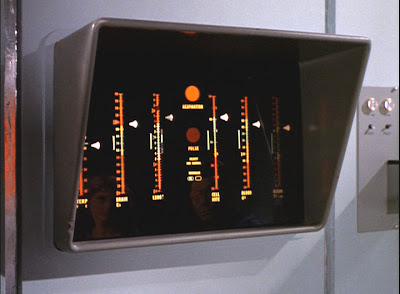
The screensaver for Quantermain is inspired, possibly on an unconscious level, by the Sick Bay vital signs display in the original Star Trek series. There are four “lanes”, one for each channel. In each lane, short lines representing the quantised pitch (on a semitone scale) scroll leftwards. The small triangles to their right move up and down to indicate the octave for that channel. Triggers (a vertical bar) and input voltages (a horizontal bar, left-going for negative voltages, right-going for positive) are indicated above each channel lane (replaced by a bit-pattern display when the sources are set to LFSR (Turing Machine) or logistic map, rather than external CV).
Example tracks
- Verhulst’s Map - a track composed and created in real-time entirely by the Quantermain app, using the quantised output of the internal Logistic map source.
- Equitable Equations and Melancholectomy- are two trackscomposed and created in real-time entirely by the Quantermain_ app, using the quantised output of the internal ByteB (byte beats) source.
This documentation has been reformatted and republished from the original Ornament and Crime manual, with permission from the copyright holders